Objective:
- Locate terminal ends and attached “add-on cables” for several 3rd-floor post-tension cables. Note areas of probable cable failure.
- Evaluate northern segment of two cable bundles on the 4th floor, each of which is accompanied by excessive cracking in the concrete slab.
Methodology:
Ground penetrating radar was used to locate, follow, and evaluate any post-tension cable continuity. Two system configurations were used. Two-dimensional line scans were produced with a SIR-3000 interface radar surveyor coupled with a high resolution 2.6 GHz antenna. Three-dimensional data grids were collected with a SIR-20 surveyor coupled with a 1.5 GHz antenna. Line scans were collected and analyzed real-time in the field, to rapidly trace and follow cables out from a known point. Data grids provided 3D depth-slice information about problem areas, suspected failure points, and add-on cable sources.
Findings:
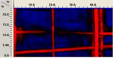
 Analysis of grid 004 is suggestive of cable failure. Directly beneath the patched section, the target reflection becomes very weak for a span of roughly 10”. However, the reflection of a deeper E/W target remains strong and contiguous, which indicates that the weak reflection is not due to attenuation of the material of the patch itself. In the image below, the N/S cable is less than 1.5” deep, while the E/W target is roughly 3”.
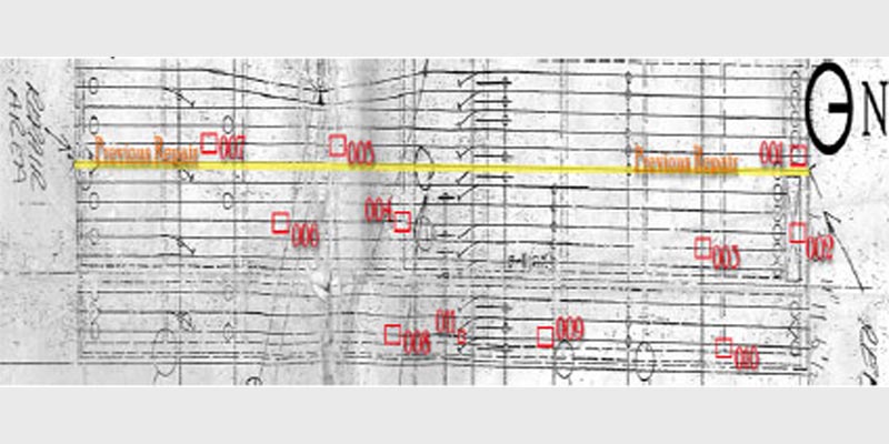
Grid series A consisted of six 4’x2’ data grids for 3D analysis. Each grid’s origin to the SE and overlapping endpoints were used to allow seamless integration. The first grid, as expected, shows two cables merging into a bundle. This bundle proceeds through the second and third grids without significant issue. Between the third and fifth grids, a small diagonal target is visible, slightly offsetting the cable bundle. In the fourth grid, at an area where the cable is rising in elevation and is most shallow in the slab, the reflection changes abruptly. This area is noted with the yellow rectangle to the left. The abrupt and significant change in the size, sharpness, and strength of the signal return suggests an area of potential cable failure.

Grid series B consisted of seven 4’x2’ data grids for 3D analysis. Grid orientation and layout as in series A. The tendon layout for this section shows four terminal post-tension cables, of which three are full-length and one is added roughly 20’ from the north wall. In grid 001, a single linear target is traveling due south almost directly beneath the surface crack. However, this target ends in grid 005 at roughly 4” deep, where a new target is picked up at 2”. In grid 001, several other targets of note are observed. Two targets can clearly be seen traveling S-by-SW and merging by the third grid. A third target joins them as well, located just west of the grid edge, barely visible in the top-left corner of 001 and the left edge of 002. The expected source of the add-on cable is roughly 26’, which should put it within grid 007. However, no cable head is visible. It is our estimation that the diagonal target circled in 007 is the add-on cable, terminating at the circled location in 001, and sourced within a few feet of the survey area. Beyond the dominant surface cracking, no suggestions of cable failure were located via GPR in this section.


